In order to run you through the process of building your own IR camera, I will use the steps taken to modify a Kodak EasyShare CX7330. It is a typical compact point-and-shoot digital camera from several years ago.
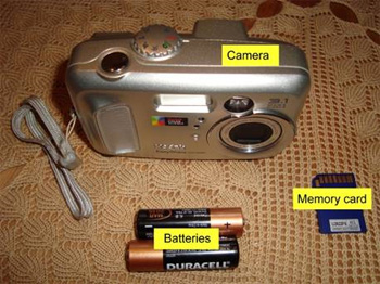
The basic components we started off with, for the modified Kodak EasyShare CX7330. It has the same feel and function as the CX6230. Note the single moving element lens housing. This will allow fitment of a filter without the use of an extension tube.
Things to keep in mind about our project requirements:
- We want the functionality of a basic IR camera at the lowest possible cost. ·
- We will do ourselves, whatever we can (to keep down costs and to learn as much as possible in the process.) ·
- We are not after flash product features, we are after functionality and utility value.
Step 1
Acquire the camera and check its workings. Cameras like the CX7330 can be bought at Internet auctions, second hand shops, etc. Many thousands of these were produced, and very few of them were used to the point of failure. You will most likely be able to pick up one which has seen very little use. Chances are, it is in pristine condition with its best years still to come. Try to get yourself a camera with a memory card, charger for the battery (if applicable), and some software for downloading the photo files included in the deal. If they are not, you may have to shop around for these. A carry case is good to have but not essential.
Once you have the camera, check to see that it actually works. Start it up and take a few photos. Do this for close-up as well as far-away objects. Shoot in different lighting conditions and at different zoom settings (if a zoom function is included). Load the files up into a photo manipulation or graphical software package and check the quality of the results. Read the handbook that came with the camera (or download such handbook from the Internet, if available). The better you know your camera and its functions, the more value you will get out of it, and the better photos the two of you will produce together. Pay attention to (and remember) the way in which the camera “comes to life” when you switch it on. Also note how user settings like exposure compensation are set.
Step 2
Set up a suitable workplace. It need not be fancy but there are a few requirements. The workplace should be clean and uncluttered, allowing you to dismantle your camera, pack out the components, and do some basic tasks, like cleaning and fitting of parts. You also need a work space (preferably some distance away from the camera building site) where you can do “dirty jobs” such as the cutting and filing of glass. Running water at this second workplace will be nice, but it is not essential. Your workplaces need to be well-lit (so you can see small parts easily) and the building site should preferably be set up such that you can leave the project there indefinitely while searching for, constructing, or waiting for parts.
Step 3
Study the outside of your camera to figure out how the shell was constructed. If possible, see if you can find a website showing you how to dismantle your camera. Most digital compact cameras are housed in a two-part shell. The shell is fixed to itself and to the innards by means of screws. The screws will most likely be of the Philips (or modified Philips) type.
Step 4
Gather the tools needed for dismantling the camera. You will most likely need a set of jeweler’s screwdrivers for the job. These are small screwdrivers with a range of shapes and sizes. The most useful of these will likely be a #00 or #0 Philips. See the photos earlier in this article for an illustration of some of the tools needed. You will most likely also need a flat-head screwdriver or two, tweezers, masking tape, blu tack, and ear bud cleaners. You will not be using the glass cutter, file, and marker right away but you may get it at the ready now.
Step 5
Remove the batteries and the memory card from the camera and store them somewhere safe. Also remove the lanyard (if there is one) as it tends to get in the way.
Step 6
Carefully remove all the screws visible on the outside of the shell. Please note that the screws may not all be alike in color, size, and shape. It may be worth your while to make a rough drawing or take photos of the camera and note which screws were removed from where. Store the screws where they will not be disturbed or lost. Be on the look-out for screws which may be hidden from sight. Sometimes screws can be found hidden under stickers or inside the battery compartment or memory card compartment. See photos showing the screws on the outside of the CX7330.
Step 7
Carefully pry open the shell of the camera. The symmetry of the shell sometimes gives away the secret as to which part should be removed first.
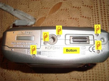
The bottom of the CX7330. There are 5 screws which need to be carefully removed. A #0 Philips screwdriver works well for the removal of all the screws on the shell of the CX7330.
With the CX7330 the back of the camera gives way. For the CX7330 there are no ribbon cables or wires joining the back to the main body. See photo.
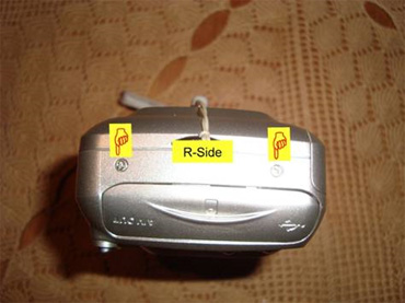
The right hand side of the CX7330. (As seen from the side with the operator interface.) There are 2 screws which need to be carefully removed.
Be aware that some of the parts inside the shell may come adrift once you open the shell. With the CX7330, there is a silver-colored metal plate which breaks away from the area where the memory card slots into the camera.
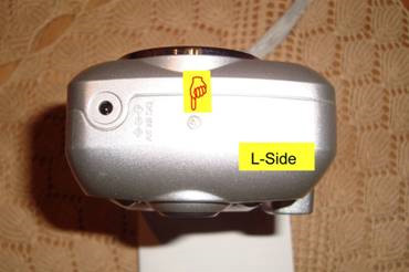
The left hand side of the CX7330. (As seen from the side with the operator interface.) There is just 1 screw which needs to be removed.
Once inside, you need to study the structure of the camera. Pay special attention to screws which obviously hold major parts together. Try not to touch the electronic components, the lens or any of the intricate mechanisms associated with moving parts. It is OK to grab hold of the camera by pressing against the sides of circuit boards. It is not OK to electrocute yourself by touching the camera flash capacitor or its circuit!
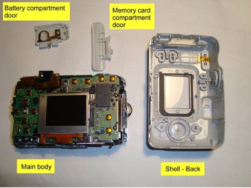
The CX7330 with its shell pried open. Note how the doors to the battery compartment and camera compartment come adrift once the shell has been split. Be careful not to touch any of the electronic circuits of the main body.
Step 8
Find the “hot filter”. The aim of the whole exercise is to find (and if necessary) replace the “hot filter”. The “hot filter” sits between the lens and the CCD. The CCD is normally mounted flat on a PC board within the camera—either the main board or an auxiliary one. The steps described below will tell you how to get to and remove the “hot filter” on a CX7330. You may or may not be able to do the same for other cameras. The hot filter of the CX7330 is located on an auxiliary board below the LCD screen. Once you open the shell of the CX7300, the LCD sits freely in its cradle on the back of the camera assembly. Gently swing the LCD out of the way to expose the cradle. Rather than proceed with the LCD screen in this awkward position, we are going to remove it. The screen is attached to the camera assembly by two ribbon connectors. (See photo.)
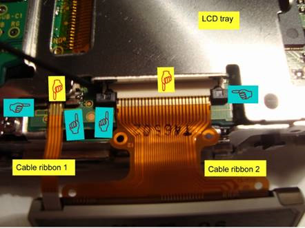
The LCD has been swung out of position and reveals the slots the cable ribbons are plugged into. Both of the connectors (yellow pointed fingers icons) are equipped with slide-in plugs. Both ends of the plugs (blue pointed fingers) need to be pulled away from the connector just a millimeter or so. (Important = Pull in a direction parallel to the surface of the PC board, not away from the board!) Doing this opens up the connector and allows the cable to be pulled from the connector freely.
The ribbon cables are both connected to the board underneath, by means of slide-in connectors. Carefully open up the connectors by pulling back on the dark colored retainer plugs until they give way. (The plugs stay in place, a few millimeters from where they were before, just allowing the plug to release the end of the ribbon cable). Gently pull both ribbon cables from their respective connectors. Now remove the three screws holding down the cradle. (See photo below.)
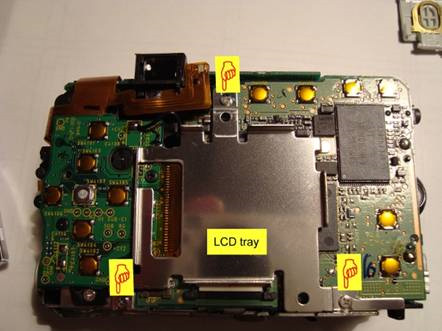
To remove the LCD tray, first remove the 3 screws shown here.
Place the screws in a safe place. Do likewise for the cradle. The auxiliary board is connected to the main board by means of a wire and a ribbon cable. The ribbon cable may now be disconnected from the main board. It slots into a connector with a swing-type retainer. The retainer opens up like a door rather than through a sliding action. Simply lift the end of the retainer to expose the end of the cable and to get the connector to let go of it. Gently pull the ribbon cable from the connector.
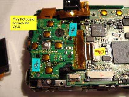
The CCD is housed underneath the auxiliary PC board shown here. First undo the two screws pointed out by the blue pointed fingers. The yellow pointed finger shows where the ribbon cable joins with the main board beneath. This connector uses a flip-up retainer to keep the ribbon cable in place. Important = Note the short length of black wire just under the view finder in the photo. Because of this wire, we will not be able to completely remove the auxiliary board. Take care not to damage this wire or its connections when you swing the auxiliary board out of position.
There are two screws holding the auxiliary board in place. Carefully remove these and place them in a safe place. If you now carefully lift and swing open the auxiliary board you will see that the CCD is mounted underneath it and that the “hot filter” sits in a recess behind the lens, between the lens and CCD. See photo.
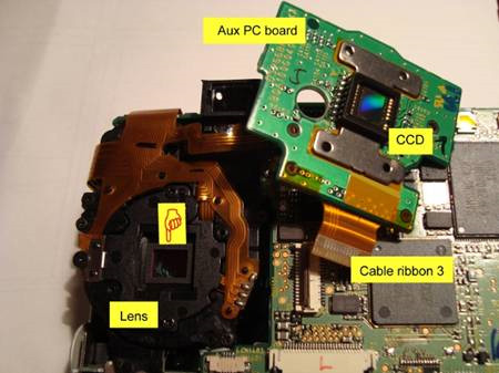
Here the auxiliary board carrying the CCD has been swung out of position. The lens assembly is revealed underneath the old position of the auxiliary board. The “hot filter” is pointed out by the pointed finger. There is a rubber seal around and on top of the filter. Remove it and the filter itself carefully.
There will be a rectangular frame-like rubber seal pressing down on the edges of the “hot filter”. Carefully remove this seal with tweezers and place it in a safe place. Using a piece of blu tack, stuck to the end of a wooden match (or similar object), press against the “hot filter” from above, and then lift the “hot filter” out of its position within the recess. You may want to leave the partially disassembled camera in its current state just where it is. Cover it with a cloth and make sure that it is not disturbed while you get to work on manufacturing a replacement filter element.
Step 9
Manufacturing a replacement for the hot filter. (Read Note 1 below before proceeding. It may be that you do not need to replace the “hot filter” at all.) The CX7330 has a “hot filter” that measures 8mm x 6.5mm x 1.1mm. If you have not previously done so, you now have to manufacture a replacement for the “hot filter” from your camera. (Read Note 2 before proceeding.) There are several sources of glass suited to the manufacture of replacement elements for the “hot filter”. Take the measurements of the “hot filter”. In some instances, where the “hot filter” floats on a rubber support, the exact dimensions are not that critical. A vernier caliper may be used to get the measures of the “hot filter” (Read Note 3).
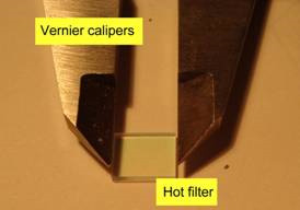
You may use a vernier caliper to get the measurements of the “hot filter”.
The filters are rather small and easy to misplace; take care! For a replacement element to fit into the recess of the CX7330, it will have to be rather close in size to the original. You now have to mark the size of the “hot filter” onto a suitable piece of glass. You may use a marker meant for writing on CD and DVD disks. The piece of glass should have a thickness as close as possible to that of the “hot filter”. It so happens that the thickness of 1.1mm was pretty close to the thickness of a microscope slide. For the CX7330 I thus marked the shape of the “hot filter” on the edge of a microscope slide. The piece of glass is then cut ever so slightly over-size and its edges are filed to get it to the same size as the “hot filter”.
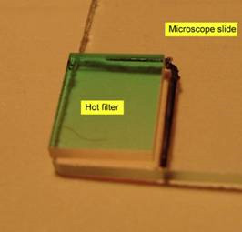
Mark the size of the hot filter on a suitable piece of glass. You may use the filter itself as template.
This process also ensures that the sides of the piece of glass will be nicely ground rather than jagged and irregular. (Read Note 4 on the cutting of glass)
Step 10
Replace the “hot filter”. Once the replacement for the “hot filter” has been manufactured, it should be cleaned properly and put back where the “hot filter” used to be. Be careful not to leave finger marks on the replacement part, not to get dirt trapped in the space between the element and the CCD and not to touch the CCD at all.
Step 11
Assemble in the reverse order of dis-assembly. Carefully reverse the process by which the camera was taken apart. Make sure that the ribbon cables are plugged in properly and locked down by means of the retainer plugs. By sure to replace every screw in the place where it came from.
Step 12
Replace the batteries and the memory card. You are now ready for a first test run of your IR-capable camera. More about the process of converting your camera, testing, and taking photos in Part 3. If you would like to fit an interchangeable filter ring to the camera you may try a modified filter ring as the interface between the camera and the interchangeable filter ring.
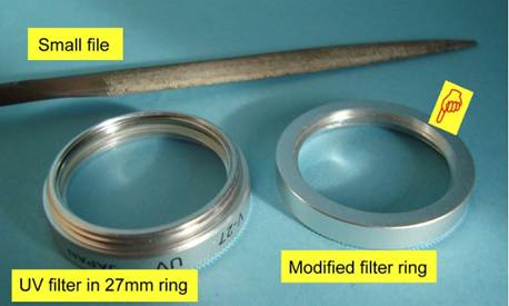
A cheap UV filter can be modified to serve at filter attachment. Remove the glass element from the original filter assembly. Then file away the male thread at the back of the filter ring. The pointed finger shows the flat surface which was created by filing away the threads. Finally sand the ring to a satin finish with fine sandpaper.
One of these modified filter rings were glued to the front of the lens of the CX7330. The fit is almost perfect and it produces a neat interface suited to our needs.
Note 1: When I modified the Kodak EasyShare CX6230, I found that no replacement element was needed for the camera to still take decent pictures. I can only assume that the absence of the “hot filter” of 0.5mm thickness did not prevent the camera from applying its auto focus function successfully. With the Nikon it was another story. The camera was not able to focus at all. After I replaced the 1.8mm thick “hot filter” with a glass element of similar size, the camera focused just fine. The CX7330 was fitted with a glass element of 1.2mm thickness. This was slightly more that the 1.1mm called for. The camera however performed quite satisfactorily.

Left: A photo taken with the Nikon Coolpix after removal of the “hot filter” but before a replacement was fitted. The camera was not able to focus at all. No IR high-pass filter had been fitted in front of the lens at this time. Right: Another photo taken from the same vantage point later that day. This was after a replacement element was fitted. The camera was now able to focus satisfactorily. No IR high-pass filter had been fitted in front of the lens at this time
Note 2: Manufacturing the glass element as replacement to the “hot filter” is by far the most difficult part of the conversion process. If you have difficulty in doing this, you may have to ask a local glass merchant or glazier to help you. They may not be used to working with such small pieces of glass but they will have glass cutters and grinders at hand. These will help immensely with the sizing and finishing of the glass element. As far as sources of glass go: the 1.8mm thick glass used for the replacement element for the Nikon, was a glass pane from a small, $2 photo frame bought at a local retailer. Internet traders sell protective covers for devices with small LCD screens. Enter “glass lens protector” as a search term and see what you get. Many of these “protectors” are glass sheets 0.5mm in thickness. These protector sheets sell for a few dollars. Microscope slides are between 1 and 1.2mm thick and easy to find through Internet trading. You can buy them by the hundred for a few dollars.
Note 3: Mention was made that you may want to use a vernier caliper to measure the size of the “hot filter”. While this may help you determine the exact measurements of the element, there is no need to invest in such calipers if you do not see yourself using them for other jobs in future. Comparative measurements will do us just fine. Look for a piece of glass “as thick as” the element from the camera (using the element itself as gauge). Then mark the outline of the element on the piece of glass by tracing it. Once cut, the piece of glass has to be shaped and brought to size. You can quite easily do this by putting the two pieces next to one another and “eyeballing” them for a fit. With the two pieces in contact with one another, your eye will easily tell you when the new piece of glass is the same size and shape as the original element.
Note 4: How to cut glass. Cutting glass is an art form of itself. It can however be mastered by the novice if you remember the following:
- Place the piece of glass on a sturdy flat surface. Cover the work surface with a clean piece of paper to protect the glass.
- Tape the piece of glass to the work surface. This is especially helpful for small pieces of glass. It protects the glass and prevents it from slipping during the cutting action.
- Mark the profile of the piece of glass you need, against one of the existing corners of the piece of glass. This leaves you with only two cuts to make. A cut should always extend all the way across the piece of glass you are working with.
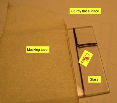
The piece of glass resting on the work surface. The intended cutting line is extended across the piece of glass.
- For our purposes, we need only cut straight lines. Use a ruler to keep the line of the cutter straight.
- Cut slightly bigger than you intend the piece to be. Breaks are never as straight as an arrow and edges are never clean cut and perpendicular to the surface of the glass element. You will need some surplus to allow for this.
- Use even pressure and “listen to the cut” when scribing the surface of the glass. The cutter or scribe makes a distinctive sound when it is cutting properly but it runs silent if it is not. A cut needs to be complete and unbroken for it to lead to a clean and straight break.
- Once you have made the cut (it is more a score than a cut), remove the piece from the work surface and place it on the top the ruler. Now line up the line of the intended cut with the edge of the ruler. Slight pressure on the piece overhanging the edge of the ruler will lead to a straight clean break along the line. Repeat this process for the next cut as well.
- Once you have obtained a piece with dimensions close to the required, file it to shape and size.
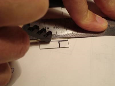
Use a ruler or other straight edge to guide the cut. Use even pressure. Pushing the cutter away from you is better than pulling it.
- The best files are constructed of metal with embedded diamond dust. They are pricier than ordinary metal files but suited to glass filing whereas metal files are not. If you do not have access to such a file, a fine sharpening stone may be used. When using a stone it works best to have the stone stationary and move about the piece of glass. ·
- Keep the surface you are filing wet (running water is best) and turn the piece of glass often to ensure that the angle on the edge stays perpendicular to the surface. If you do not use running water, dunk the work piece often, submerging it completely and giving it a good shake each time you take if from the water.·
- Test against the original often to ensure that you do not go under size. Small pieces of glass like the ones we are working with here, are best held in the hand while filing. (See photo) Do not try to clamp a piece of glass. ·
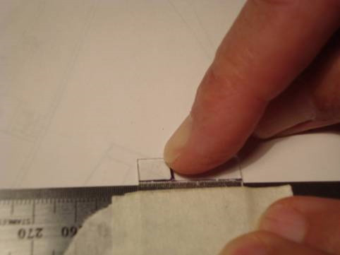
Properly scored glass will break under the lightest of pressure
- Be careful when cutting and shaping glass. Glass shards (even very small ones) are dangerous and can lead to ugly cuts, skin irritations, and injuries to the eye. Flying shards are very hazardous and you should always wear protective glasses when cutting or shaping glass. Clean the work area carefully after working with glass and dispose of unused pieces of glass responsibly.
- Do not be discouraged if your first attempt fails. Working with glass is like that. You may have to go through several attempts to get a suitable piece of glass. ·
- Watch out not to scratch or otherwise damage the flat surfaces of the replacement element. The element is, after all, destined to serve as an optical element in your camera and will only produce acceptable results if it is kept clear of scratches and other blemishes.
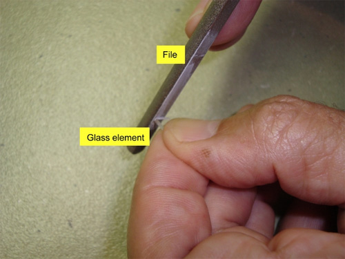
Once you have cut a slightly oversized replacement glass element, you need to file it down to size. This is the most laborious part of the whole modification ! Use water to cool the piece of glass and to wash away debris. (In this staged photo the ground glass particles had been allowed to dry. Try to avoid this during the actual filing process).
Part 3 – How to build your own IR camera – Selecting the IR part of the light spectrum
Part three of the article assumes that you have completed part two and have produced an IR ready camera. By this we mean that your camera now is capable of registering light in both the visible and near infrared spectrum. (Up to and even exceeding 1000nm)
Step 13
Checking the basic functionality of our camera. (The rest of this article assumes that you have, at the ready, a camera that has had its “hot filter” removed and replaced with a glass element similar to the filter which was removed. It assumes this camera to have auto focus and the ability to set different exposure levels or modes.)
Switch on your camera and check the basic functions. Does it “come to life” the way it used to. (It may ask you to set a date and time. That is an annoyance but quite normal for cameras which have been without batteries for a certain period of time.) If the camera does not “come to life” the way it is meant to:
- You may have to replace the batteries.
- You may have to check and alter settings in the set-up menu to get it to go properly.
- You may have to open it up and check to see that all mechanical as well as electronic functions are still intact. Did you properly plug in all the cables which were disconnected? Are all components back in place where they were meant to have gone?
- The camera may have been damaged or may have failed in another way.
If your camera fails to fire up properly after the conversion, do what you can to get the problem resolved. If unable to do so, the project has unfortunately failed for you. Either try again with another camera or walk away with the knowledge that at least you learned a few things and at least you tried.
Step 14
Confirming the ability to take useful photos. Now try to take photos the same way you did when first you checked the camera. Take a few photos of close-up as well as far-away objects. Do it in different lighting conditions and at different zoom settings (if a zoom function is included).
Do not be surprised if the picture on the LCD screen looks out of sorts. We expect this picture to have a red hue to it. The reason for that is that the red channel in your camera now gets overloaded. If all has gone well during the modification, the camera now senses visible as well as IR light at comparable levels. (Previously the IR component was seriously restricted by the “hot filter”.)

One of the test photos taken with the CX7330. There was no IR high-pass filter in front of the lens yet. The photo was taken in bright sunlight at high noon. The shutter speed is recorded at 1/1024 sec. The tree is showing signs of the Woods effect even before the removal of the light in the visible spectrum. The 3 MP CCD is already showing its superior definition. Maybe because of this, the photo started to show differences in the “focus” for centrally placed subject matter VS off-axis subject matter.
Load the files up into a photo editor and check the quality of the results. The colors may very well be out of whack (red or pink or something similar) and you may find that the pictures are a bit fuzzier than they were before. One of the reasons will be that the camera is trying to focus on a large range of wavelengths and can not do so successfully. The ability to focus depends on the type of lens and the algorithm of the auto focus program. There should be a sense of normality to the pictures and some attempt at focusing from the camera at least. (Maybe not for all of the photos but for some at least.) If the camera passes this test, we may proceed to turning it into a proper IR camera.
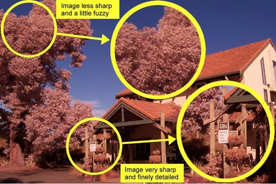
A perceived difference in the sharpness of off-axis subject material may have to be investigated. It can be that the lens is not coping so well with off-axis imagery. It may be that the IR filter is flawed or that the home-made replacement element for the “hot filter” is flawed. For the CX7300 the over-all quality of the photo was still quite acceptable.
Step 15
Limiting the spectrum of light being captured.
Most photographers prefer their IR photos to capture a reasonable amount of the distinctive features of IR light. We want to see the Woods effect in foliage and we want to see dark skies. We want to have sharp contrast in our photos and we want the ghostly effects seen in classic IR photos. In order to achieve those effects, we need the ability to cut down on the amount of visible light being captured in our photos. We thus either have to build a filter into the camera (I decided not to do that) or we have to devise a way of supporting a high-pass filter in front of the lens.
For the Kodak CX6230 used in my project, I simply glued a 27mm threaded filter to the front of the lens. (See photo earlier in this article.) This filter-and-filter-ring combination leaves us with a filter which is non-interchangeable. For the purposes of introductory IR photography this is quite sufficient. You may decide to do the same. If you do, the choice of filter is up to you. Higher numbered filters give more IR effect but they may limit the amount of light let through the lens (and thus push us toward longer exposure times). Lower numbered filters will allow through more light but may show less of the IR effects we are after.
For the Nikon, I had to improvise a different filter holder. The Nikon extends its lens in two parts. I was unable to mount the 27mm filter ring on the smaller inner tube of the lens assembly. I did however manage to mount it on the second tube of the lens assembly. I had to allow some space for the inner tube to extend into. A short length of aluminum pipe was thus called for, connecting the filter ring to the front of the second tube (See photo of the Coolpix.) It leaves us with a longer protrusion sticking out of the camera. It also limits my field of view as it causes a small amount of vignetting on my photos at certain zoom values.
For the CX7330 I decided on an interchangeable filter. Once again a filter ring was glued to the lens but the filter itself was removed from this ring. Other filters can now be screwed into this ring allowing us to change filters. See photos showing the modified filter ring which was glued to the front of the lens (toward the front of this article) and photo of completed camera with interchangeable filter fitted (photo shown below).
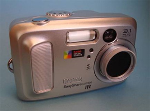
The completed CX7300 IR. Note the fixed filter ring and the interchangeable filter ring attached to the front of the lens. The lay-out is still very neat, compact and practical.
Step 16
Take the camera out on a photo shoot.
If your camera has the capability to do manual white balancing you may want to set that before taking photos. (This is explained briefly later in the article.) In any event, you now need to take your camera, complete with filter attached to lens, out into the wild to take your first photos.
Choose a sunny day and see if you can capture the following:
- Foliage and greenery. Try trees, shrubs and lawns.
- Water and sky
- Stone and/or brick structures
- Steel or other metals
- People and household objects
Depending on whether the white balance on the camera has been adjusted, the LCD screen may or may not show a picture with a red hue. It does not matter right now. Frame your pictures and get those shots. Once again take a few photos of close-up as well as far-away objects. Do it in different lighting conditions and at different zoom settings (if a zoom function is included.) You may even try to adjust the exposure setting on some of the photos. If possible, make notes on which settings were used for which photos. This will help you analyze the results at different settings and will go toward your understanding of your camera and its capabilities.
Step 17
Download the photos to a computer.
Do not be alarmed if the IR photos you download are colored red or purple or the like. Keep in mind that there are no “colors” beyond the visible spectrum. What we transfer to the computer is merely data on light intensities captured in three channels. These channels happen to be colored red, green, and blue to coincide with the primary colors used for visible light photography. Once you have downloaded this information into your photo editor of choice, you can start manipulating it to create a B/W photo or a false-color photo of your liking.

One of the first photos taken with the modified CX6230. The purple hue is not a problem at all. The photo contains mainly light with a wavelength longer than 850nm. Such light is not purple and your final IR photo need not be purple ! It is left up to you make something interesting out of the information contained in the .JPG-file.
Step 18
Evaluate, learn, and utilize. With any luck, you now have the tools and the knowledge to take your own IR photos. You may have to refer to articles on the manipulation of digital images to get the final results you are after. If, however, you proceed, and do so successfully, you may be pleasantly surprised with the results. I will be pleased as well. Together we have proven that it is possible to do IR photography on a low budget and that cheap homemade IR cameras are capable of producing stunning results.
Included in this article are just a few photos I have taken with my cameras. They go some way to illustrate the point. I prefer to work in grayscale but my cameras are able to produce the raw picture data for grayscale as well as false-color IR photos. You can try both.
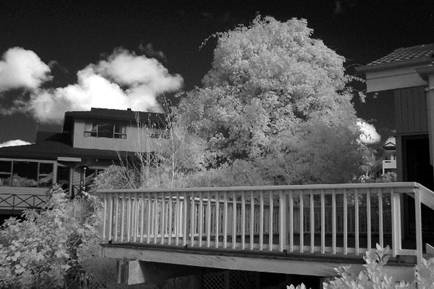
Photo taken with CX7330. 850nm high-pass filter fitted. Shutter speed recorded at 1/128.
Remember the photos used to illustrate Note 1 in Part 2 of the article? The photo shown here was taken from the same vantage point. It was taken with the CX7330 after fitment of an 850nm high-pass filter. It was a sunny day but there was some high cloud. The recorded shutter speed was 1/128. Note the dark sky. The photo appears to be slightly under exposed. Another photo taken with a 950nm high pass showed even darker sky and a more pronounced Woods effect. For that photo the recorded shutter speed dropped to 1/64. Details in both were quite satisfactory and the results were what I aimed for.

Photo taken with CX7330. 850nm high-pass filter fitted. Late afternoon sun. Shutter speed recorded at 1/256. Off-axis focus not too good. Results quite useable.
At the time this article was written, I have not had the time to properly utilize the CX7330. The photo above was taken in a local park in late afternoon sun. A number of interesting elements are contained in the photo; trees, water sky and clouds are all visible. I am sure that with some experimentation and under the right conditions this camera will serve all of my IR photography needs.
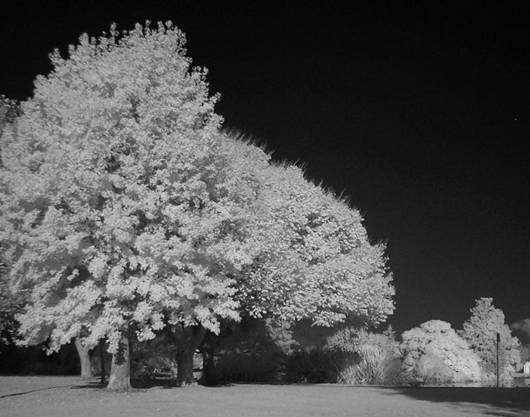
Photo taken with CX7330. 850nm high-pass filter fitted. Direct late afternoon sun. Shutter speed recorded at 1/362. Central focus pretty amazing. The artistic value of this photo is very low. I am excited about this photo for another reason – to me it proves that pretty good photos can be taken with this camera under the right circumstances!
Another experimental photo taken with the CX7330. In this photo the sky came out almost pitch black and the focus in the middle of the photo was spot on. I can’t wait to take this camera on a proper photo shoot!
Good luck with your camera conversion projects and may you see the light—the infrared light!
Notes to be read with Part 3:
Note 5: The Nikon Coolpix allows the photographer to set the white balance before the photo is taken. This is rather helpful to the IR photographer. A typical IR-modified camera may not be able to set color balance correctly on its own. Due to this problem, the IR-modified camera may sometimes over-expose one channel (typically the red) and under-expose another channel. If your camera allows for manual white balancing this problem can to a great extent be overcome. The process is very easy. You start by selecting the calibrating option from the camera’s menu. With the desired IR filter in place in front of the lens, and in the same lighting conditions you aim to take the photo, you simply aim the camera at a gray surface and press the shutter button. The camera recognizes and measures the amount of light registered on each of the channels and balances it out. Once this set point has been calculated and set on the camera, the color reproduced in your photo’s will be “neutral” (for the specific lighting conditions we have now set). You will immediately notice that even the picture shown on the LCD screen now appears more natural and very little manipulation will be needed during post production.
Other lessons learned and useful pieces of information:
- At the time of writing, the Kodak EasyShare CX7300 IR cost less than $60 all-up. I got a memory card as part of the original purchase and the replacement glass element was manufactured from a microscope slide I was given for free by a guy I know from work!
- Even though GIMP is free, it does some jobs better that the fancy software aimed at photo manipulation. If you use GIMP for the processing of your IR photos, you will find that the EXIF information of the photo is preserved afterward. The EXIF information is valuable to the IR photographer, as it helps you keep track of some of the settings on your camera at the time the photograph was taken. You can read the EXIF information of a photo file when it has been downloaded onto your computer. To see the EXIF of the photo file, right-click on the file, go to Properties, and open up the tab labeled Summary.
- In my haste to get my cameras up and running I forgot to set the date and time properly. An omission like this may come back to haunt you later. Photos stored on line carry this.
- If you build up an IR camera with white balance capability you will have the opportunity to set the white balance before each shoot. Do so by all means.
- The pictures you get from your camera will not be perfect. I have had minor problems with vignetting and with poor focus of the picture for off-axis objects on some of my photos (see examples). If you consider the complexity of optical systems and the physics of ray tracing, this was to be expected. The lenses in the cameras we use here were not designed for the long wave lengths we are using them at. The effects of diffraction and the fact that we have interfered with the optical elements within the light path, all work against us. IR photography however is about “capturing the magic of the hidden picture”. It is about artful composition and about imaginative use of what we have got. If you want really good looking IR photos, you can always crop away the edges, you can try a different angle during the shoot or you can give it another go tomorrow. Remember to always look out for those special IR photo moments and keep pressing that shutter button as many times as it takes!
Acknowledgements
I would like to acknowledge two people who were instrumental in the success of my project and in getting this article “to press”: ·
- My wife has in the past had to endure a lot because of my projects. Our house is forever cluttered with half-finished projects, tools around every corner and weird parts (which may not be disturbed !) on every work surface. She however remains my greatest supporter and needs special mention for the fact that she battles on, looking after me and the household, despite the fact that I make it very difficult for her. ·
- I have also had lots of support from Peter Holder. I know him from work and we sometimes share stories about the crazy projects we each have been involved in. Peter supplied some of the motivation and some of the components for this project.
About the author:
Pieter Albertyn is a self-confessed “tinkerer” and amateur photographer. He lives in Napier, New Zealand. Pieter has previously been involved in product development and systems engineering. He loves to modify utility products, enhance their features and develop basic logistical support systems for them. Though he works in an English dominated workplace, English is his second language.
Like This Article?
Don't Miss The Next One!
Join over 100,000 photographers of all experience levels who receive our free photography tips and articles to stay current:





Hello, I just wanted to know if the Kodak EasyShare CX4300 is also a good replacement for the CX7330/CX6230?
I love articles like this. Almost two dozen steps, with all kinds of disassembly, modification, hacking, rebuilding, testing…
Or you could just get a decent film camera and put some IR film in it.
Hello people, infrared is not the same as thermal !!!!!!
I bought an infrared filter years ago and hardly ever use it so refitting a camera with it seems to be a bit over the top for me, but for one who uses it regularly this is a great option
I followed ur steps, camera functions on, menu etc. But I have no images on the lcd or I’m the memory – I can delete from memory but I physically cannot see any image as I am taking photo on the screen. Any idea what went wrong
Best thermal Cameras
is this automatically dark sky after put 850nm high pass filter..??? or you editted it in computer sir..?? i’ve already same project with it,, making dark sky and visible to vegetation, water or other ..?? thanks alot
I had no idea that a thermal camera could be made from home. I like the idea of having a thermal security camera on the perimeter of my home so I found this guide interesting. I think buying a professionally made and installed thermal camera would be best for my needs but I appreciate the interesting post.
Can this be used to see humans in the dark?
My wife is already fed up with the camera bits everywhere. I’ve already ruined one perfectly good camera (that’s another story, trying to make it lighter). My first attempt at IR conversion is a Dimage Z5 (5Mp, my previous camera). I have removed the filter over the sensor, put it back together and it works but it can only focus at macro distances. I checked with an IR remote and it is WAY more sensitive to the light emitted than a Nikon D3200, so I know I am on the right track. All I need is a 1.5mm piece of glass…
I’m a bit discouraged though as I have already wrecked one camera although that had nothing to do with IR conversion. Also, my R72 filter just arrived for my non-converted D3200 and I am quite disappointed with the results.
Apparantly the Dimage 7 is very good as an IR camera, so So I will continue with this Minolta Z5, it sounds as if I am half way there. I think I’ll just order a cheap UV filter, they should be about 1.5mm thick, right?
Wahyu, Im afraid thermal imaging is out of reach for amateur photographers – these cameras cost from 2000 USD up and are for special aplications like finding hotspots on buildings etc. You have to keep in mind that “thermal” IR has wavelength 3500 nm and longer, but our converted cameras are sensitive only to about 1000 nm depending on model. So there is no way your sensor could detect thermal radiation in any meaningful way.
Leslie – I know that (and my girlfiend especially :) I have several half finished projects lying around waiting for parts to arrive or the right mood (and some spare time) to finish them. One I did last year was converting mirrorless nx100 for IR following instructions from Paulshome blog (google: pauls home infrared nx100) and results are very good. You can get it with 20-50mm lens pretty cheaply today (even refurbished) and can only recommend this camera for IR. Only downsides are the kit lens (very sharp) is very prone to flare in IR, but i have since learned to cope with that, and it tends to get a bit more noisy on higher ISO then im used to (but still way better then PNS). Now I have few lenses, NX20 as main camera and NX100 as IR / backup (putting IR blocking filter instead of IR pass filter restores “normal vision”).
Anyway… Infrared is great fun!
good article. please more article about IR camera with thermal imaging. how can i do that?
It works very different than a band filter in a camera.
Thermal cameras uses amplification effect and its not cheap to build or buy.
I did this with a EasyShare C300 I had laying around and I didn’t replace the ir filter, and everything came out fuzzy because it’s a fixed focus. I’ll fill the space with some microscope cover slips.
Right, I forgot to tell you why I left the filter off. Infrared light focuses through lenses at different lengths than visible light. The focusing issue is one reason why most camera manufacturers put the filters there in the first place. I thought I might get lucky and have the focus dead on by the slight distance change but I was wrong. Anyway, the change in focus point of infrared wavelengths could be cause of your decreased sharpness in step 14. Just a thought.
Hi, great article! I odified” – well, opened up and tore out the hot filter – my Finepix AV100. It’s 12Mpix PnS. I didn’t even need to replace hot filter (it was about 0,5-1 mm thick, but I didn’t take exact measurements). The camera focuses fine and I did the whole disassembly / assembly thing in less than an hour so I can recommend this camera for modding.
This is an awesome article! Thanks so much for writing it. I helped my daughter make an IR camera for her science fair, and the results were great!
One thing to note – a low cost IR pass filter can be made using developed, but unexposed slide film (E6). The black blocks visible light but passes IR. Here’s an article about it http://www.pixiq.com/article/create-your-own-ir-filter.
Thanks again!
Nice tutorial! I have a CX7300 that I modified a while ago. Instead of buying an IR filter (high pass filter) to put on it I just replaced the in-camera filter with 2 layers of blacked out film negative. That works fairly well too.
My thanks to PictureSocial management for the work done on this series of articles. There was a lot of re-formatting and cleaning up which needed to be done. I intend to iron out a few wrinkles in due course. Readers are also invited to comment on errors and/or ommissions. I will endeavour to deal with them all in time.